

Preventing the ‘Jetstream effect’ in HPLC flow measurements
Hizkia A. Chandra, Carlo Dessy, Testa Analytical Solutions e.K.

Determination of flow rate and comparison of the obtained results with expected or nominal values, is a very common task in liquid chromatography. It is also very often part of the validation of an HPLC/UHPLC system, as commonly required by labs following OQ/PQ guidelines. Among the methods available, modern non-invasive flowmeters are without a doubt the most flexible and capable tool for the task, as by nature they can deliver flow rate data with high accuracy and resolution in real time thus providing additional information as pulsation or short-term instability. As such, careful selection of a flow device used for the measurement is paramount for exploiting the full possibilities offered by such a powerful tool.
It is widely acknowledged in HPLC, that any pump requires a minimum of back pressure to operate to its stated specification. The reason for this is not completely clear and explanations to be found are more than nebulous. It is, however, a generally accepted reality. In the context of flow rate measurement for validation of a single pump, the required back pressure is usually generated by connecting a length of a narrow bore (0.1mm to 0.25mm) restriction capillary to the pump outlet. For example, a tubing ID 0.17mm and a length of 600mm, will generate a back pressure of around 0.5 MPa at 1mL/min and 1.2 MPa at 2.5 mL/min, both using pure water as eluent at 25 °C. These pressures are in general considered sufficient to assure perfect operating conditions for the pump. Surprisingly, however, flow rate measured directly at the outlet of the restriction capillary, often leads to erroneous results, a fact that we investigate in this paper.
To better understand this phenomenon, and take corrective measures, we need to first understand the measurement itself. When “flow rate” is to be measured, we really mean the measurement of the total volume flowing through the system per unit of time. Fundamentally, we are measuring the volume of the liquid passing through the flowmeter within any given time. As such, we assume that the total volume of fluid flow is in permanent movement at the very same, or at least constant, velocity. We now need to keep in mind that the velocity profile of a moving liquid within a capillary tube is defined as laminar flow (see Fig. 1).
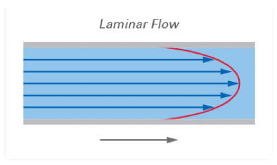
In a laminar flow all velocity vectors are not equal across the whole section of the tubing, but they are consistently constant. Therefore, determination of flow rate as defined before is possible, using non-invasive flowmeters. However, a problem arises when a phenomenon known as "Jetstream" occurs.
The term "Jetstream" describes how the flow profile (more accurately the velocity profile) is affected by an abrupt change of tubing ID, when the change is from a narrow bore to a significantly larger bore. Such an abrupt change in ID causes a “core stream” to be built in the larger ID tubing leaving the liquid layers closer to the wall of the tube practically unperturbed (see Fig. 2 below). The reason for this is to be found by nature of the flowing liquid. The liquid exits the narrow bore tubing at a relatively high velocity, and it takes quite a while for this energy to dissipate and reach the level required in the large bore to produce the same effective volume stream. As an example, at a flow rate of 1 mL/min, the stream velocity within a 0.17mm ID tubing is around 0.73 m/sec while with tubing ID 1.6mm, the velocity is just 0.008 m/sec. This shows clearly how the internal diameter (ID) of the tubing affects velocity of a stream of liquid.
![Jetstream Velocity Vector [1]](papers-images/illus-47.jpg)
The Jetstream effect will decisively affect the velocity profile of laminar flow and will create disturbances which will affect measurement of HPLC flow rate.
This flow disturbance can originate from various sources, including flow of liquid from narrow to large bore tubing, or channels in the capillary with constrictions or restrictions, valves and fittings and even sharp bends in the tubing can disrupt the flow, leading to the formation of Jetstreams.
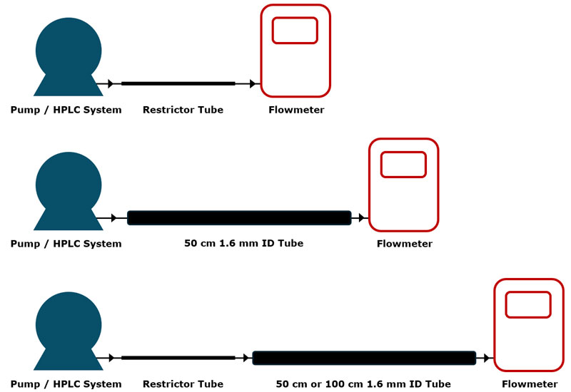
To make flow rate measurements of liquid from an HPLC Pump fitted with a tubing restriction (e.g. valve) we recommend inserting a tube with larger ID between the restrictor tubing and the flowmeter. This will mitigate the impact of the Jetstream by providing more room for the flow to stabilize before reaching the flowmeter. For sake of clarity, this large bore tubing may be defined as the “relaxation tubing”- The relaxation tubing helps dissipate the energy of the Jetstream, reducing turbulence and fluctuations in flow velocity. As a result, the flowmeter receives a more consistent and stable flow, leading to more accurate measurements.
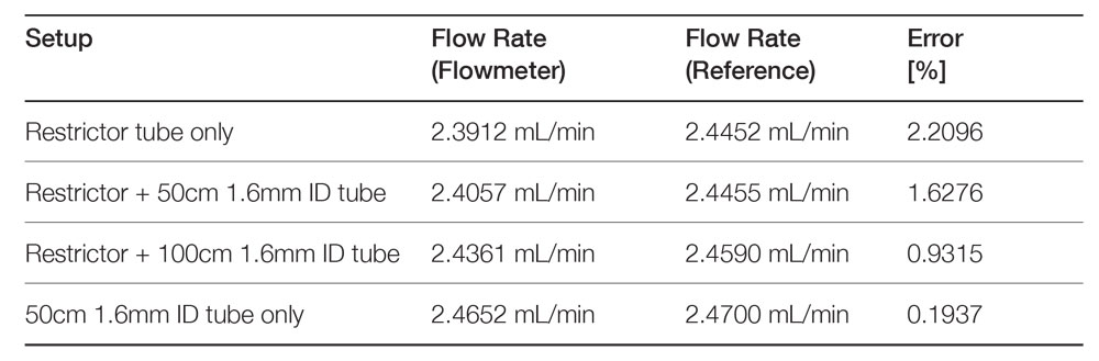
The following measurement data (Fig. 3) demonstrates the influence of a length of the relaxation tubing on the accuracy of the flowmeter reading.
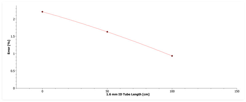
Employing linear regression analysis to extrapolate the relationship between tubing length and flow measurement accuracy, it is recommended to use a relaxation tubing length of 150 cm to achieve accurate measurements at 2.5 mL/min.
However, it is important to note that for lower flow rates, the Jetstream generated by the fluid may be proportionally smaller. Consequently, a shorter relaxation tube length may be sufficient to achieve accurate measurements.
Conclusion
The above experimental data makes it very clear how the restriction tubing, required by the HPLC/UHPLC to assure perfect performance, is a primary source of the Jetstream effect which negatively affects accurate measurement of flow rate. The use of appropriately dimensioned relaxation tubing, however, will compensate in full for this Jetstream effect thereby ensuring the precise performance of a connected non-invasive flowmeter.
Thank You!
Your message has been forwarded to our team and we will reply as soon as possible. Thank you for your patience.
© 2026 TESTA Analytical Solutions e.K. All rights reserved.